

4·
2 days agosome people say it’s august 8 then august 20

some people say it’s august 8 then august 20
Huh weird. There must be something evil in that pole, it might be a piece of metal or maybe it’s wet or rotting inside. I’d use plastic things to tie it, because natural fibers will remain wet some time after rain, that might degrade performance. (zipties or nylon fishing line or whatever preferably monofilament). I see that bottom is secured too, this is good because in wind antenna could flap around and would stop working if it’s too close to the pole. If twin lead is slightly twisted and under strain (half turn per 30cm or so) then it should flutter less in wind, but you’ve got it spliced and i’m not sure how that would work. This is likely fine as is
J-pole type antennas are effectively monoband. They might work on 3rd harmonic which would be here 70cm band, but most of signal in this case goes up and down that is it’s useless and the signal that goes out horizontally is 6db weaker than what it would be with J-pole for that band. So you can take more precise measurement by zooming in to 130-160MHz or even 140-150MHz, this way you’ll see how low does SWR go at band edges because now you can only see that there is minimum somewhere in the band. I don’t know how much your radio tolerates, but 1:1.5 is generally pretty good. On receive only it might be good also at other frequencies, but dedicated antenna would be likely better
I don’t know if you have calibrated your VNA with cable or not, you can use Smith chart if you do calibrate it with cable but without it, SWR shouldn’t change too hard with any reasonable length of cable (Smith chart rotates once per half wavelength of feedline). This is useful especially if you make your own antennas, but here it’s fine just to make sure that SWR is low
we don’t do magic, don’t call it enchanting circle
you see, you can be as wrong as you want to be. i won’t be teaching you middle school level chemistry against your will in a comment section. in concrete Ca2+ remains Ca2+, be it as hydroxide or carbonate or silicate and it cannot become reduced in normal concrete conditions and definitely it can’t be oxidized.
The Calcium Carbonate degrades into Calcium Oxide
no it fucking doesn’t, this is what happens when cement is prepared in a kiln. near surface of curing concrete calcium hydroxide captures carbon dioxide from air, then this crust of precipitate blocks it from moving deeper. which is why the rest of calcium hydroxide reacts with silica forming calcium silicate, which takes more time and is responsible for late strengthening. before you lost plot i was talking about oxidation of steel rebar, and it depends on many things, but for regular carbon steel if there’s no oxygen then it’s much slower. and because concrete is not very permeable to oxygen, there are all these engineering requirements about how deep rebar has to be. anyway, a little bit of vinegar would be just neutralized by calcium hydroxide from concrete and won’t do anything, a little bit of salt would be diluted massively and also won’t do anything, hydrogen peroxide would decompose because anything will do that
have you calibrated your nanovna? you have to do that after every change of frequency range. you need S11 smith chart, not S21 smith chart (port 2 is not connected). swr and logmag get you the same info in different formats, pick 1
1m away from metal things should be okayish but the more the better. these lights will interfere, if you could at least move them away from the corner it would be an improvement. twin lead cannot be close to metal either (is that sheet metal near bottom of antenna?) needs at least couple cm of distance from it. i would also replace that nail with a ziptie
strictly speaking that’s a slim jim. why does it have a twist in the middle? untwist it, the radiating part (upper approx 1m) should be a smooth transmission line for it to work right (or shorted at both ends)
If you want to preserve the way it’s made, you’d need to resolder the top bar after adjustment. But you also can leave wires on top unconnected
there are also more damage-susceptible things in a datacenter
calcium carbonate is still basic and even hydrogen carbonate is basic enough to be protective against steel corrosion
The Calcium Carbonate once dissolved in water will start to form the Calcium Hydroxide layer on the surface, thats the alkaline layer, and deeper in the carbonation creates acidity.
100% wrong, how come there’s more carbon dioxide inside than outside, you’re starting from calcium hydroxide and silicate. on the surface there’s some carbonate formation from carbon dioxide, but when it can’t get there calcium silicate forms instead. either way both are basic
coated rebar isn’t, it’ll always get dinged somewhere. stainless is expensive and the real available scalable option is either galvanized or sometimes basalt fiber, or glass fiber but i’ve not heard about it too much. the most important factor in slowing down corrosion is how thick concrete layer is on top of rebar, because concrete is very slightly porous and will let oxygen in, but the thicker that layer is, the slower oxygen gets to rebar, then the slower corrosion is, and this means it takes longer for rust layer to grow enough for concrete around rebar to fail due to swelling, because rust takes more volume than corroding steel
a bit of vinegar might strip zinc layer, but won’t do too much and definitely it won’t matter long term until most of zinc layer is gone. salt also promotes corrosion but this also depends on oxygen availability and won’t be too fast, it would only matter if there’s salt in concrete in large amounts
these things can corrode rebar slightly
concrete is calcium carbonate and silicate, both are basic. it’s also slightly porous but mostly waterproof by itself, doesn’t matter that hard in this application since there will be AC removing water from the inside 24/7 anyway
it’s more turbines, not sure if it’s the same site or another
That’s just the legal limit, i think we’re looking more at microwatt range or lower. Somebody on stackexchange measured power output of phone nfc module, and - measuring power received at secondary of air-core transformer - got 0.8mW. Assuming it’s representative, if all that power was fed into phone-sized magloop (10 cm square made out of 6 mm copper pipe) then at this frequency (13.65 MHz) we’re getting some -30dB efficiency so 800 nW. This is already very charitable overestimate, because NFC antenna is smaller, thinner, printed and multi-turn, and does not behave like magloop at all. Any response from passive device would be much weaker still. All of that uses high data rate (wiki says that ISO/IEC 14443 says 106 kbps), and because these things are where people live, there will be also a lot of urban noise. I’m not saying it’s impossible, but it wouldn’t be that easy
HF ISM bands as used (NFC things etc) are probably in sub-mW power range, there are regulatory limits on field strength and 27 MHz is additionally limited to 10 mW EIRP. Unless you have curtain that can hear signals from the future i don’t think there’s a lot to listen
This will be good for renewables. Every solar inverter and wind turbine needs this stuff
No, width is your design parameter. I’ve used 4mm wire because store ran out of 5mm wire, but 3mm would be fine too if you can make it work mechanically. Were it all in air with no plastic, width of both is such that impedances of matching section are close to 300 ohm. Plastic around it lowers impedance and makes wire appear longer. 2m antenna has 220 ohm matching section and it also works. Rectangular connection boxes also work but the ones i could get weren’t as stiff. The way it’s done, bottommost section can be clamped with a regular pipe clamp, it’s harder with a box. Either way 4 or 5mm is not thin on 70cm so impedance of dipole will be probably lower than 5000 ohm, and entire band is covered so it just works
Pick any material you’re comfortable with. Start with 1 wavelength + couple cm of wire, measure out 1/4 and bend it so that 1/4 length point ends up at the bottommost point. Tune by trimming (both arms, lengths of shorter and longer should stay 3:1) and match by moving feedpoint lower or higher (lower is lower impedance). That’s why I’ve made them this way, you can see marks from screw near feedpoint because feedpoint was moved a bit both sides during tuning. By the time trimming gets minimum SWR close to say 420MHz adjust feedpoint to get minimum SWR then alternate between trimming and adjusting feedpoint if necessary. Every mm counts, small trims are better done by filing the wire down instead of cutting it. Plastic needs to stay on during measurement. Keep some 1m of free space (without large metal things) around antenna during measurement
Paging @tasankovasara@sopuli.xyz for logistically efficient antennas
Most of the magnetic flux should be contained in ferrite, and the part that leaks is pointed at the middle of other ferrite so it shouldn’t induce anything. This is fine
exactly, the ferrite only affects common mode current. you can think of coax as being composed of 3 conductors, core, interior of shield and exterior of shield. above some frequency and below frequency where coax starts to work like a waveguide, internal surface and core carry opposite currents (differential mode), and external surface carries common mode current. these can be treated as separate, except at the ends, because of skin effect. but also you can use twisted pair, because differential mode currents cancel out there
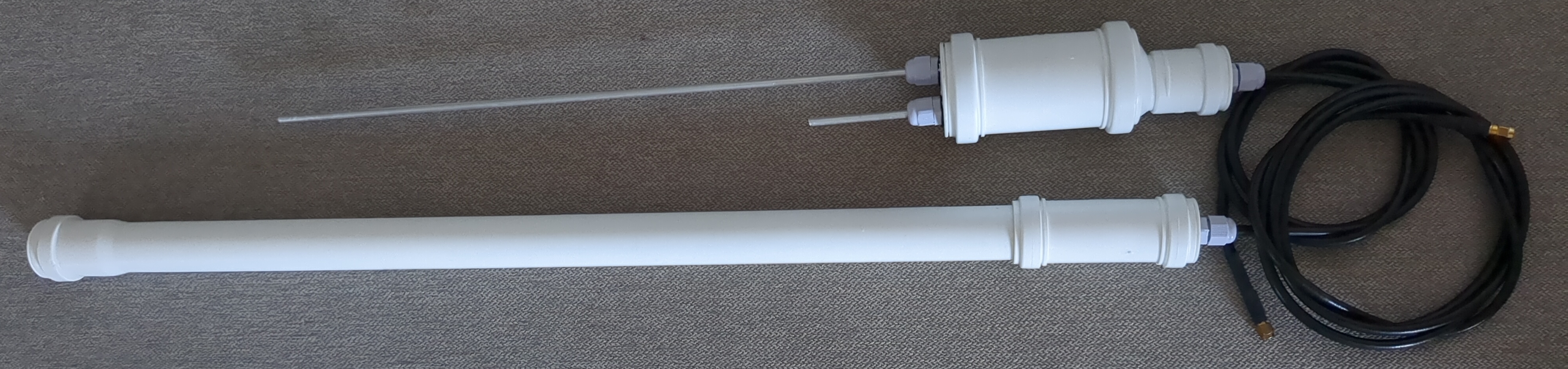
that’s just a piece of wire, perhaps some thin steel rope in a heatshrink attached to center conductor and trimmed to length. 1/4 wave at 2m which is fine, 3/4 wave at 70cm which means it’ll radiate most of energy upwards (wasted) when put on a conductive plane. this works because the other half of antenna is low power, handheld radio and operator (coupled by hand capacitively). putting 100W into it would be a bad idea because all that current will travel along the coax down to radio and operator except this time there’s an option of rf burns. for this kind of money, i’ve made two jpoles with extension cables, and the most expensive part was enclosure
i’ll make a post over the weekend about j-pole antennas that i’ve made recently. one of them even looks halfway professional

botnet builders don’t care, and they’re doing this because they started at some point and nobody stopped them